 40G/100G Optical Transceivers
 25G Optical Transceivers
 10G Optical Transceivers
 155M/2.5G Optical Transceivers
 1G Optical Transceivers
 1G BIDI Optical Transceivers
 Dual-Rate Optical Transceivers
 FC 16G/32G Optical Transceivers
 CWDM Optical Transceivers
 DWDM Optical Transceivers
 SGMII Port Optical Transceivers
 XFP Optical Transceivers
 100M/1G/10G Coppers
 Full-Rate AOC & Breakout Series
 10G/40G Active DAC Series
 Full-Rate Passive DAC Series
 40G/100G Passive Breakout DAC Series
 Regular/MTP-MPO Fiber Patch Cords
 MT2011
 MT2010
 CodingBox
 QSFP to SFP Adapter
 首页 > Home > Application Notes > How To View Port Status And Optical Transceiver Information On Arista Switches
How To View Port Status And Optical Transceiver Information On Arista Switches
Time: 2024-06-06
Reading internal transceiver parameters allows monitoring of link status, real-time TX/RX optical power, temperature and coding compatibility between modules and Arista switches. This document takes Moduletek SFP-10G-LR transceiver connected to Arista DCS-7160-48YC6-F switch as an example to demonstrate complete parameter query procedures.
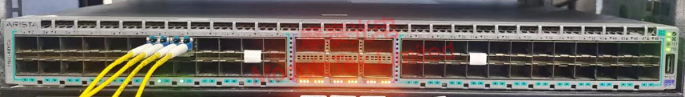
Figure 1 Schematic Diagram of Optical Transceiver Connected to Switch
1. View Port Link Negotiation Status
Run the command:
show interfaces <interface-name> status
It displays port speed, duplex mode, transceiver type and link status. Connected status means normal link operation.
Note: interface-name is the physical port ID. Run show interface status to view all ports. Omitting parameters will output full interface status.
If port type does not match actual transceiver model, run command
show interfaces <interface-name> transceiver hardware
to compare configured media type and real module type.
Mismatched media type will not disconnect the link directly, but cause abnormal DDM data reading. For example, 10G LR module identified as 10gbase-cr will fail to collect DDM current parameters.
You can manually adjust media type with command
transceiver media override type [target type]
Note: Transceiver type is auto-detected by default. Manual configuration commands vary by switch model and system firmware version.
2. Query Transceiver EEPROM Encoding & Hardware Identification Data
Run the command:
show inventory
It shows overall device hardware list, including power supplies and transceivers, with vendor name, part number, serial number and hardware version.
Run the command:
show idprom transceiver extended
It reads A0h & A2h EEPROM encoded data, helping engineers accurately troubleshoot transceiver hardware faults.
3. Check Real-Time Transceiver DDM Threshold & Fault Diagnostic Data
Run the command:
show interfaces <interface-name> transceiver detail
It presents real-time DDM values and upper/lower alarm thresholds. You can judge abnormal operation of transceivers on both ends by whether parameters stay within the safe range.
Moduletek provides a full range of transceivers compatible with Arista switches. Welcome to inquire and purchase.
For further inquiries about the above content, please contact us at: sales@moduletek.com


