 40G/100G Optical Transceivers
 25G Optical Transceivers
 10G Optical Transceivers
 155M/2.5G Optical Transceivers
 1G Optical Transceivers
 1G BIDI Optical Transceivers
 Dual-Rate Optical Transceivers
 FC 16G/32G Optical Transceivers
 CWDM Optical Transceivers
 DWDM Optical Transceivers
 SGMII Port Optical Transceivers
 XFP Optical Transceivers
 100M/1G/10G Coppers
 Full-Rate AOC & Breakout Series
 Full-Rate Passive & Active DAC Series
 40G/100G DAC & Breakout Series
 Regular/MTP-MPO Fiber Patch Cords
 MT2011
 MT2010
 CodingBox
 QSFP to SFP Adapter
Introduction to 3D testing of fiber optic connector end faces
Time: 2024-07-15
3D testing is a critical test to ensure the performance of fiber optic connectors. When producing fiber optic patch cord assemblies, manufacturers use 3D interferometer (which is an optical interferometry instrument) to check the fiber optic connector endface and strictly control the dimensions of the connector endface.The 3D test mainly measures the radius of curvature, vertex offset and fiber height. Details are as follows:
⦁ Curvature Radius
The radius of curvature is the radius from the insert axis to the endface, as shown in the figure below, which is the radius of the curve of the ferrule endface. The radius of curvature of the end face of a high quality fiber optic patch cord connector should be controlled within a certain range. A radius of curvature exceeding the lower limit of the standard will put more pressure on the optical fiber, while a radius of curvature exceeding the upper limit of the standard will not be able to put pressure on the optical fiber, which will lead to the connector and the optical fiber end face of the air gap (i.e., air gap). A radius of curvature that exceeds the test standard results in light scattering or insufficient physical contact to ensure excellent transmission performance. Only a proper radius of curvature will ensure proper pressure application and excellent transmission performance.
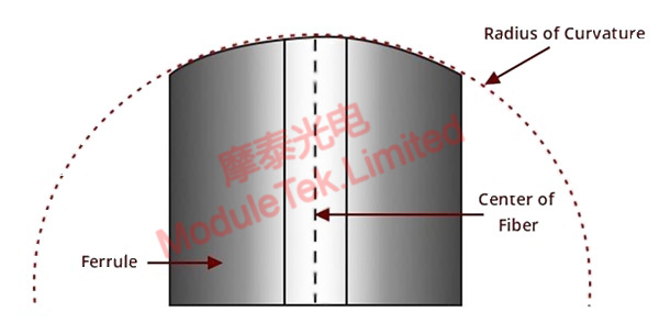
Figure 1 Radius of curvature for 3D testing
⦁ Vertex Offset
Vertex offset is the distance from the highest point of the core face curve to the axis of the fiber core after grinding and polishing. This is a critical item in the polishing process, and inaccurate polishing can lead to vertex offset.
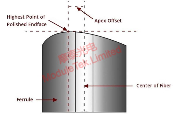
Figure 2 Vertex Offset for 3D Testing
⦁ Fiber Height
Fiber height is the distance from the end face of the fiber to the section of the ferrule, which is the extended height of the core to the end face of the ferrule. High-quality fiber optic patch cord connector end face of the fiber height should be controlled within a certain range Similarly, the fiber height can not exceed the standard range. If the fiber height is high and standard, when docking two fiber optic connectors will increase the pressure inside the fiber, thus damaging the fiber; if the fiber height is lower than the standard range, when docking two fiber optic connectors will produce a gap, resulting in increased insertion loss. This is important to avoid for transmissions with strict insertion loss requirements.
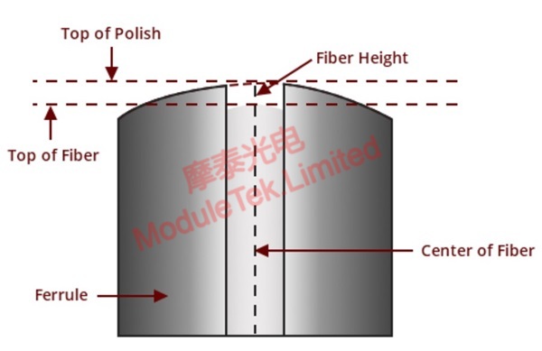
Figure 3 3D test of fiber height
Moduletek Limited is at your service!
If you have any questions about the above content, please contact us via email: sales@moduletek.com


