 40G/100G Optical Transceivers
 25G Optical Transceivers
 10G Optical Transceivers
 155M/2.5G Optical Transceivers
 1G Optical Transceivers
 1G BIDI Optical Transceivers
 Dual-Rate Optical Transceivers
 FC 16G/32G Optical Transceivers
 CWDM Optical Transceivers
 DWDM Optical Transceivers
 SGMII Port Optical Transceivers
 XFP Optical Transceivers
 100M/1G/10G Coppers
 Full-Rate AOC & Breakout Series
 Full-Rate Passive & Active DAC Series
 40G/100G DAC & Breakout Series
 Regular/MTP-MPO Fiber Patch Cords
 MT2011
 MT2010
 CodingBox
 QSFP to SFP Adapter
 首页 > Home > Application Notes > How to choose MPO patch cords and MPO adapters for 40G 100G parallel transmission optical modules
How to choose MPO patch cords and MPO adapters for 40G 100G parallel transmission optical modules
Time: 2024-01-17
The common 40G 100G multimode and singlemode parallel transmission optical modules on the market are 40G-SR4/PSM4, 100G-SR4/PSM4 and so on. After customers buy these modules, how should they purchase MPO patch cords and MPO adapters when organizing networks? Or, how do we manage the polarity of MPO patch cords to match these optical modules in practical applications?
MPO patch cords and MPO adapter types are clearly defined in the TIA568 standard.
The MPO jumper type (Array connector cable Type) has three wire order definitions, A/B/C:
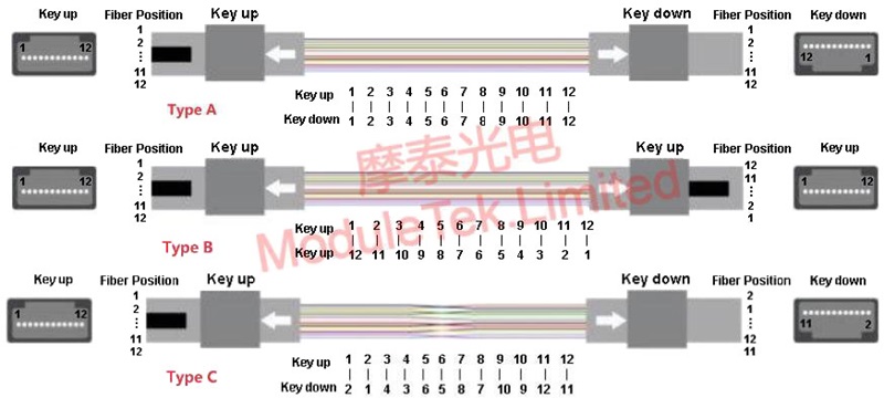
Figure 1 MPO jumper cable type A/B/C
Type A (Key up-Key down) straight-through patch cords use straight-through fiber bundles with keyed-up MPO connectors and keyed-down MPO connectors at each end, with the same fiber optic counterparts at each end of the patch cord;
Type B (Key up-Key up) full crossover patch cords use a reversed fiber bundle with keyway up MPO connectors at both ends, and the fibers at both ends of the patch cord correspond to opposite positions;
T ype C (Key up-Key down) wire-pair crossover patch cords use wire-pair crossover (Cross Pair) fiber bundles with keyway up MPO connectors and keyway down MPO connectors at both ends, and the two fibers adjacent to one end of the patch cord correspond to opposite positions of the two fibers adjacent to the other end.
MPO adapter type (Array adaper Type) is used to connect two sections of MPO patch cords, there are also two types, A and B. Type A refers to Key up-Key down matching at both ends of the adapter, and Type B refers to Key up-Key up matching at both ends of the adapter.
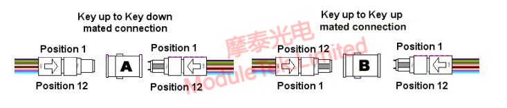
Figure 2 MPO Adapter Types A and B
When 40G-SR4/PSM4, 100G-SR4/PSM4 and other parallel transmission optical modules are organized in a network, MPO patch cables will be used to connect from the optical modules, and then interconnect with the external MPO backbone fiber optic cables through MPO adapters for transmission. There are two common connection methods, and the corresponding line configuration methods are listed in the following table:
Table 1 Line Configuration
|
Connection method
|
MPO backbone cable type
|
MPO adapter type
|
MPO patch cord type
|
|
1
|
A
|
A
|
One end A, one end B
|
|
2
|
B
|
B
|
B
|
Connection Method 1 A typical connection schematic is shown below. On the left side, two MPO interface optical modules can be connected as the signal transceiver, and the modules are connected to the A type MPO adapter through one A type MPO jumper cable and one B type MPO jumper cable respectively, and then fed into the MPO backbone fiber optic cable of the link A type, to complete the polarity management of the whole optical circuit. type depending on the type of the optical module, matched for use.
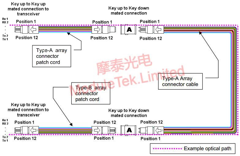
Figure 3 Diagram of connection method 1 for parallel signaling
The typical connection diagram for connection method 2 is as follows. The fiber polarity in this case is relatively simple, all use B-type MPO fiber optic patch cords and backbone fiber optic cables, with B-type adapters can be. Special attention should be paid to the fact that because the B-type adapter is a Key up to Key up structure, so the MPO jumper end face at both ends of the adapter must be a 0-degree angle, not APC beveled.
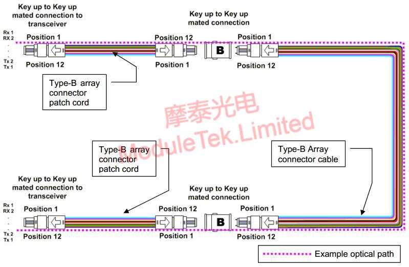
Figure 4 Schematic diagram of connection method 2 under parallel signaling
In other words, when using the parallel optical module QSFP-SR4 or QSFP-PSM4 for networking, you can purchase A-type backbone fiber optic cable with A-type MPO adapter, one A-type fiber optic patch cord and one B-type fiber optic patch cord, or you can purchase all B-type fiber optic patch cord and backbone fiber optic cable with B-type MPO adapter. The polarity of the first method of fiber optic purchase is easier to confuse, the second method of fiber optic purchase is more convenient, so usually customers in the purchase of optical modules with MPO patch cords, most of the use of B-type MPO fiber optic patch cords.
From this, we can also derive the following two relatively simple parallel optical module QSFP-SR4 or QSFP-PSM4 interconnection:
1. two modules are interconnected by only one fiber optic patch cord, which must be used with B-type fiber optic patch cords;
2. two modules are interconnected by two fiber optic patch cords with an MPO adapter, you can choose two B-type fiber optic patch cords + a B-type MPO adapter, or two A-type fiber optic patch cords + a B-type MPO adapter, or an A-type fiber optic patch cord + a B-type fiber optic patch cord + an A-type MPO adapter.
Moduletek can provide 40G, 100G full series of multimode and singlemode parallel transmission optical module products, also can provide a variety of line type multimode and singlemode MPO patch cord products, welcome to buy.
If you have any questions about the above content, please contact us via email: sales@moduletek.com


