 40G/100G Optical Transceivers
 10G/25G Optical Transceivers
 155M/622M/2.5G Optical Transceivers
 100M/1G Optical Transceivers
 FC 16G/32G Optical Transceivers
 CWDM/DWDM Optical Transceivers
 100M/1G/10G Coppers
 Active Cable AOC
 Direct Attach Cable DAC
 Regular/MTP-MPO Fiber Patch Cords
 MT2011
 MT2010
 CodingBox
BOX package EML TOSA introduction
Time: 2020-02-23
⦁ General Description
40km and 80km 1550nm optical module transmitter using EML (Electro-absorption Modulated Lasers) TOSA, commonly used EML TOSA BOX package and coaxial package, but taking into account the heat dissipation and performance, commonly used or BOX package form, in this paper I would like to introduce you to BOX package EML TOSA structure and its working principle. In this article, I would like to introduce the structure of EML TOSA in BOX package and its working principle.
1. BOX TOSA Outline Structure and Internal Function Diagrams
BOX TOSA Outline Structure
As the name suggests, BOX TOSA is a BOX type with large internal space. Figure 1 below shows the dimensions of the BOX EML TOSA that is currently used by our company in large quantities:
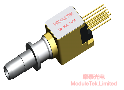
Figure 1 BOX EML TOSA dimensions of the external structure of the diagram
As shown in the above figure: BOX EML TOSA has a total length of 17.6mm, the length, width and height of the TO are 7.5mm, 5.5mm and 5.5mm respectively, the space inside the TO cavity is relatively large, so that it can be used with a large package of TEC (Thermo Electric Cooler), and the outer wall of the TO is a 0.8mm alloy material, which has good heat conduction and dissipation characteristics.
2. Block Diagram of BOX EML TOSA Internal Functions
BOX EML TOSA consists of five parts: DFB laser, EAM, MPD, TEC and Rth. It is shown in the figure below:
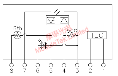
Figure 2 BOX EML TOSA Internal Circuit Diagram
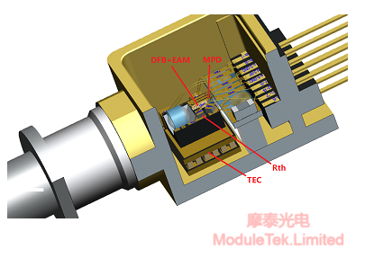
Figure 3 Schematic diagram of internal structure and function of BOX EML TOSA
As shown in Figure 2 above, this is the internal circuit diagram of a typical EML TOSA, and Figure 3 is a schematic diagram of the internal structure and function of a typical BOX EML TOSA, and we will introduce to you in detail the specific working principle and control method of each functional circuit below:
A, DFB laser, Distributed Feedback Laser, Figure 2 above between pin 7 and pin 5 is the DFB laser, where pin 5 connects to GND, pin 7 input current, when the pin 7 input current is greater than the threshold current (15-30mA) when the DFB laser begins to emit light, normal operation of the DFB laser needs to be added to the current of 50-100mA.
B, EAM (Electro-absorption modulator), the Chinese abbreviation for the electro-absorption modulator, Figure 2, foot 4 and foot 3 is between the EAM, which is the third foot ground, the fourth foot needs to be connected to a negative voltage (0 ~ -3V during normal operation) to make the EAM reverse bias, when the fourth foot of the voltage is more hours of the EAM absorbs the light more, the less light through the EAM. When the voltage at pin 4 is small, the more light is absorbed by the EAM and the less light passes through the EAM; conversely, when the voltage at pin 4 is large, the more light passes through the EAM, and the typical EAM absorption curve is shown in the following figure:
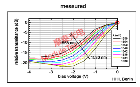
Figure 4 EAM absorption characteristic curve
C, MPD (monitoring photodetector), Figure 2 above, between pin 6 and pin 3 is the MPD . Used to monitor the size of the DFB laser light-emitting, in general, there is a certain percentage of the DFB light emitted in the opposite direction (we usually call "backlight") irradiated to the MPD, resulting in the MPD current, usually the size of the MPD current and the size of the DFB laser front light-emitting into a proportional correspondence, so by monitoring the current of the MPD can track the DFB laser. Therefore, by monitoring the current of MPD, we can track the size of the light emitted by the DFB laser.
D, TEC ( thermoelectric cooler), Figure 2 above, between the first and second foot is the TEC. According to the "Peltier effect" made when the DC current flows through the two semiconductor materials composed of the phenomenon of electric coupling, one end of the heat absorption, one end of the exothermic phenomenon. TEC includes a number of P-type and N-type pairs (group), they are connected together through the electrode, and sandwiched between the two ceramic electrodes; when there is a current from the TEC, the current generates When a current flows through the TEC, the heat generated by the current will be transmitted from one side of the TEC to the other, generating ″hot″ side and ″cold″ side on the TEC; the current size and direction on the TEC is dynamically adjusted by the TEC controller according to the temperature on the surface of the TEC, so as to make the temperature of the surface of the TEC maintain a dynamic and stable state.
E, Rth ( thermistor ), above figure 2, between the 8th and 5th pin is Rth. Its resistance value and temperature have a corresponding relationship, the higher the temperature, the smaller the resistance value, the lower the temperature, the larger the resistance value. At 25℃, the resistance value of Rth is equal to 10K ohm. Rth generally forms a dynamic feedback regulation system with the TEC controller, which dynamically adjusts the current through the TEC through the PID control algorithm to stabilize the operating temperature of the TEC surface ( DFB/EAM ).
Moduletek Limited offers the products covered in the above application guide.
If you have any questions about the above content, you can contact us by Email : web@moduletek.com


