 40G/100G Optical Transceivers
 10G/25G Optical Transceivers
 155M/622M/2.5G Optical Transceivers
 100M/1G Optical Transceivers
 FC 16G/32G Optical Transceivers
 CWDM/DWDM Optical Transceivers
 100M/1G/10G Coppers
 Active Cable AOC
 Direct Attach Cable DAC
 Regular/MTP-MPO Fiber Patch Cords
 MT2011
 MT2010
 CodingBox
Introduction to two common unlocking methods for Optical Modules
Time: 2023-12-01
⦁ Background
Optical module is a key component used in optical communication and optical network equipment for optoelectronic conversion and optical signal transmission. With the continuous development of optical communication technology, the optical module profile is evolving to miniaturized SFP packages, and the following figure shows several typical optical module packages:
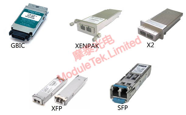
Figure 1 Several kinds of optical module package outline diagram
For 25Gbps and below, SFP is the mainstream package.
SFP optical modules usually support hot-swap, optical module insertion and removal with the SFP cage has an unlocking action, the current mainstream two unlocking methods are sunken and push-pull, we briefly introduce these two ways.
⦁ Sinking type
The core of the sinking type unlocking is to pull the ring pulling process, driving the optical module shell triangle locking device sinking, and SFP cage detached to achieve unlocking, Figure 2 is the ring is not pulled up, in the locked state of the photo:

Figure 2 Sinking unlocking scheme - locked state
Figure 3 is a photograph of the module in an unlocked state with the pull ring pulled up:
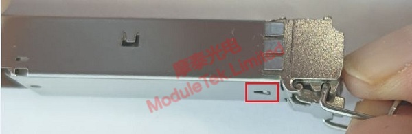
Figure 3 Sunken unlocking scheme - unlocked state
Figure 4 is a structural assembly of 1 sunken unlock enclosure in conjunction with an SFP cage:
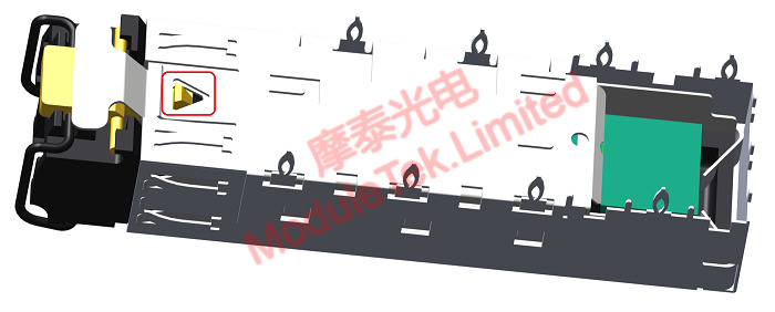
Figure 4 Assembly diagram of the sunken unlocking scheme-housing with SFP cage
⦁ Push-Pull
The core of push-pull unlocking is that during the pulling process of the pulling ring, some parts on the housing push the locking structure position on the cage upward, and disengage from the triangular locking device on the module to realize the unlocking, Fig. 5 is a photo of the pulling ring not being pulled up and in the locking state:
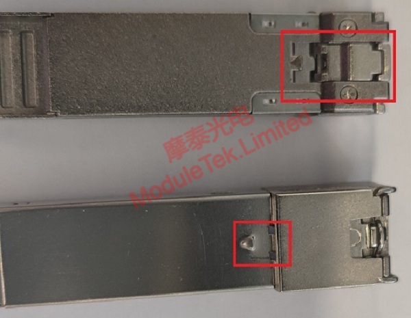
Figure 5 Push-pull unlocked-locked state
Figure 6 is a photograph of the pull ring pulled up and the module in an unlocked state:
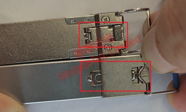
Figure 6 Push-pull unlocked-unlocked state
Figure 7 is a structural assembly diagram of 1 push-pull unlock enclosure with SFP cage. The pull ring is pulled up and part A moves to jack up the cage B position to realize the unlock:
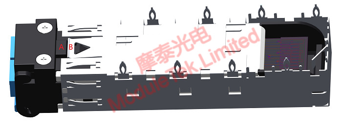
Figure 7 Assembly diagram of push-pull unlocking solution-housing with SFP cage
We can provide SFP optical modules with the above two unlocking methods, welcome to buy !
If you have any questions about the above content, you can contact us by Email : web@moduletek.com


