 40G/100G Optical Transceivers
 25G Optical Transceivers
 10G Optical Transceivers
 155M/2.5G Optical Transceivers
 1G Optical Transceivers
 1G BIDI Optical Transceivers
 Dual-Rate Optical Transceivers
 FC 16G/32G Optical Transceivers
 CWDM Optical Transceivers
 DWDM Optical Transceivers
 SGMII Port Optical Transceivers
 XFP Optical Transceivers
 100M/1G/10G Coppers
 Full-Rate AOC & Breakout Series
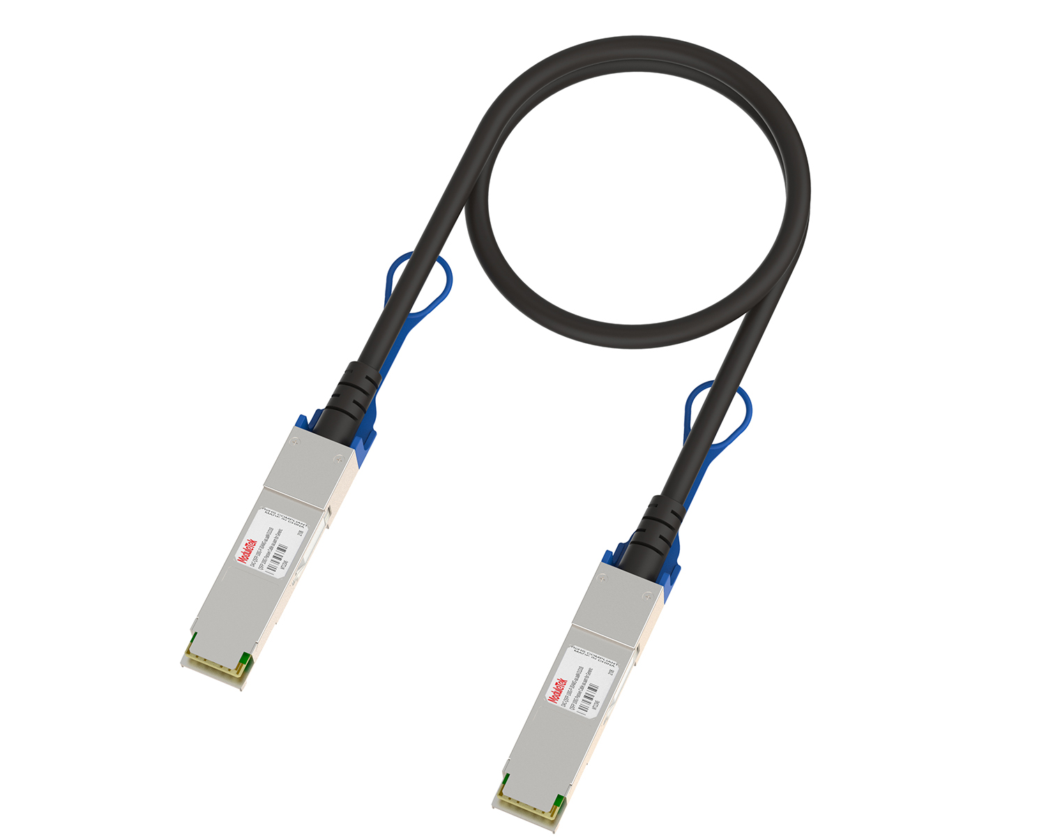 Full-Rate Passive & Active DAC Series
 40G/100G DAC & Breakout Series
 Regular/MTP-MPO Fiber Patch Cords
 MT2011
 MT2010
 CodingBox
 QSFP to SFP Adapter
DAC cable encyclopedia
Time: 2021-11-09
In data centers, short-distance, high-speed, and high-reliability interconnection transmission is required between equipment such as high-performance computers and large-capacity storage. A commonly used transmission solution is DAC (Direct Attach Cable). This article briefly introduces the basic concepts of DAC.
I. What is DAC?
DAC, short for Direct Attach Cable, is generally translated as Direct Attach Cable or Direct Attach Copper Cable. It is a cable assembly with fixed connectors at both ends, usually purchased in fixed lengths, and is divided into two types: Passive DAC (Passive Copper Cable) and Active DAC (Active Copper Cable). DAC transmits electrical signals and does not involve electro-optical or opto-electrical conversion.
Passive DAC: It adopts shielded high-speed differential copper cables, with no chips on the circuit boards at both ends, and no signal processing during the entire signal transmission process (see Figure 1). As the preferred solution for short-distance applications, it is commonly used for data transmission between the same or adjacent cabinets in data centers. Its core advantages are low cost, ultra-low power consumption (less than 0.1 watts), and high reliability.
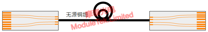
Figure 1: Block Diagram of Passive Copper Cable
Active DAC: Similar to passive DAC, it also uses shielded high-speed differential copper cables, but is equipped with high-speed electrical signal compensation chips (for pre-emphasis, equalization, etc.) internally. These chips compensate for the attenuation of electrical signals during transmission, enabling longer-distance data transmission between devices such as switches without compensation functions (see Figure 2). Compared with passive DAC, its biggest features are thinner cables and longer transmission distance.
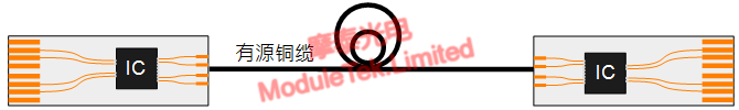
Figure 2: Block Diagram of Active Copper Cable
II. DAC Structure
• High-Speed Cable Structure
The high-speed shielded differential cable connecting the two modules of DAC plays a key role in the overall performance of DAC, and its structure has an important impact on alignment performance.
Figure 3 shows a typical single-ground structure of 2-pair high-speed cables, mainly used for SFP-type DACs that require single transmit and single receive. The core is the high-speed line, made of silver-plated copper wire, wrapped with an insulating foam layer. A pair of high-speed wires, the insulating foam layer, and the ground wire are wrapped by an aluminum foil shielding layer to form a differential transmission line structure. The material, wire diameter, and process of this structure have a decisive impact on key parameters of the cable, such as insertion loss, reflection, and delay.
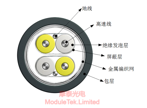
Figure 3: Typical Single-Ground Structure of 2-Pair High-Speed Cable
The outside of the two pairs of differential wire harnesses is covered with a metal braided mesh and an outer sheath. The metal braided mesh acts as a shielding function, while the outer sheath mainly plays a protective and reinforcing role. Common sheath materials include PVC and low-smoke zero-halogen (LSZH) type. The color is usually black, but can also be customized to other colors.
Figure 4 shows a typical single-ground structure of 8-pair high-speed cables, which is similar to the 2-pair structure. It is mainly used for QSFP-type DACs that require 4 transmitters and 4 receivers.
Figure 4: Typical Single-Ground Structure of 8-Pair High-Speed Cable
• Introduction to Terminal Modules at Both Ends
The module interfaces at both ends of DAC are the same as those of ordinary optical modules, mainly including two types: SFP and QSFP. Their structures are as follows: Figures 5 and 6 show the structures of SFP+ and SFP28 type terminals, while Figures 7 and 8 show the structures of QSFP and QSFP28 type terminals.
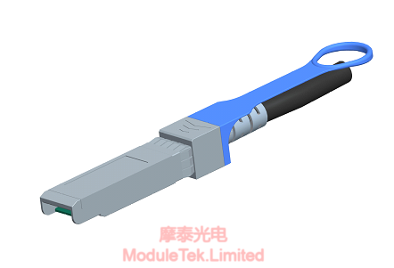
Figure 5: Outline Structure of SFP-Type Terminal Module
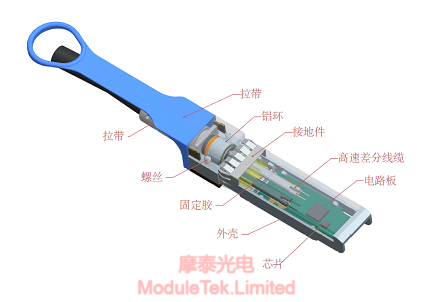
Figure 6: Structural Decomposition of SFP-Type Terminal Module
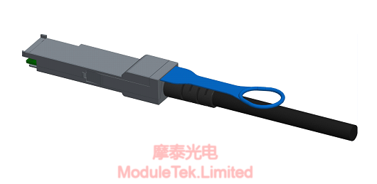
Figure 7: Outline Structure of QSFP-Type Terminal Module
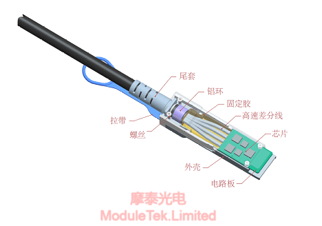
Figure 8: Structural Decomposition of QSFP-Type Terminal Module
III. Common DAC Types
• SFP-SFP
SFP-SFP DAC mainly includes 10G-rate SFP+ to SFP+ DAC and 25G-rate SFP28 to SFP28 DAC. Its appearance is shown in Figure 9.
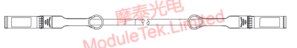
Figure 9: SFP-SFP DAC
• QSFP-QSFP
QSFP-QSFP DAC mainly includes 40G-rate QSFP+ to QSFP+ DAC and 100G-rate QSFP28 to QSFP28 DAC. Its appearance is shown in Figure 10.
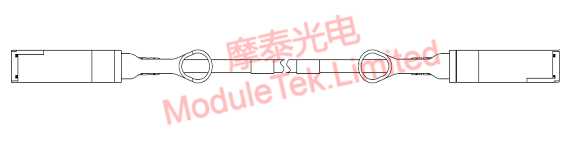
Figure 10: QSFP-QSFP DAC
• QSFP-4SFP
QSFP-4SFP DAC mainly includes 40G-rate QSFP+ to 4×SFP+ DAC and 100G-rate QSFP28 to 4×SFP28 DAC. Its appearance is shown in Figure 11.
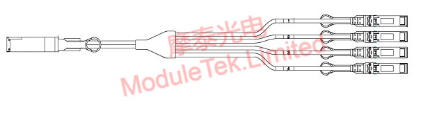
Figure 11: QSFP-4SFP DAC
IV. Comparison of Different Cables
Conventional short-distance interconnection cables include Passive DAC, Active DAC, and Active AOC (Active Optical Cable). They have different advantages, disadvantages, and corresponding application scenarios. The following table compares the key parameters of DAC and AOC to help customers select suitable products:
Table 1: Parameter Comparison of Passive DAC, Active DAC and Active AOC
|
|
Transmission Medium
|
Wire Diameter
|
Transmission Distance
|
Power consumption
|
Cost
|
|
Passive Copper DAC
|
Copper Wire
|
Thick
|
Short (≤10m)
|
Ultra-low
|
Low
|
|
Active Copper DAC
|
Copper Cable
|
Medium
|
Medium(≤15m)
|
Medium
|
Medium
|
|
Active Optical Cable AOC
|
Optical fiber
|
Fine
|
Long(≤30m)
|
High
|
High
|
V. Summary
This article briefly introduces the basic concepts of DAC to help customers gain a preliminary understanding. For in-depth insights into practical application issues, follow-up content will be provided.
Moduletek provides the products mentioned in this application guide. Welcome to place your orders!
If you have any questions about the above content, please contact us via email: sales@moduletek.com


